Atmospheric Optics - Dan Bruton

The purpose of this page is to provide introductory information for students interested in atmospheric optics. The software link below can be used to download and Mueller Matrix software.
[ MUELLER MATRIX DEMONSTRATION SOFTWARE ]

Note: Richard Hill [rkhill@caci.com] provided the following info:

The definition of Stokes Vector components on (this) site is in error. Wolfram has it wrong also. The easiest way to see that it is wrong is to take horizontally polarized light (1, 1, 0, 0) and solve for the intensities. The total intensity I0 is ½ and the horizontal intensity I1 is 1. That obviously doesn't add. The Wikipedia explanation is consistent (Lord help us).

S0 = I0 = I(horizontal) + I(vertical)

S1 = I(horizontal) - I(vertical) = 2*I(horizontal) - I0

S2 = I(+45) - I(-45)

Please correct as desired.
Thanks, RK

Mueller Matrix Information - June 2002

Definitions

Stokes Vector
The original Stokes parameters were defined by letting
I0 be the total intensity,
I1 the intensity of horizontal linear polarization,
I2 the intensity of linear polarization at a 45° angle, and
I3 the intensity of left-handed circularly polarized light, and then defining
S0 = 2I0
S1 = 2I1 - 2I0
S2 = 2I2 - 2I0
S3 = 2I3 - 2I0
So the Stokes vector is      

Table 1: Stokes Vector Examples

PolarizationStokes Vector
Unpolarized
Linear Horizontal
Linear Vertical
Linear +45°
Linear -45°
Circular, Right-Handed
Circular, Left-Handed

Mueller Matix

Optical elements can be applied to Stokes vectors using Mueller matrices. The Stokes vector describes the polarization of a plane wave, and the Mueller matrix describes how the polarization changes upon scattering at a change in electrical or magnetic properties.

The Mueller Matrix contains everything optically one can obtain from a system of scatterers in a turbid medium. It is a matrix that can be used to reproduce the effect of a given optical element when applied to a Stokes vector.

Table 2: Mueller Matrix Examples

Optical Element Mueller Matrix
Clear Filter
Linear Horizontal Polarizer
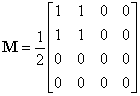
Linear Vertical Polarizer
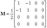
Linear Polarizer at +45°
Linear Polarizer at -45°
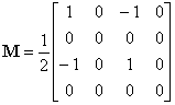
Quarter-Wave Plate,
Fast Axis Vertical
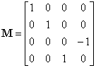
Quarter-Wave Plate,
Fast Axis Horizontal
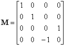
Circular Polarizer,
Right-Handed
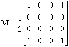
Circular Polarizer,
Left-Handed
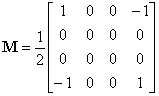
More Definitions

Radiance (or brightness)
The brightness is the intensity of a radiating source (i.e., the energy flux per solid angle per unit of frequency), also called the radiance or surface brightness. In MKS, it is measured in units of J m-2 s-1 Hz-1 ster-1.

Irradiance (or flux)
The flux of a quantity is defined as the rate at which this quantity passes through a fixed boundary per unit time. In various contexts, flux is called the exitance, irradiance, or radiancy. Energy flux, one of the most common types encountered, has units of energy per unit area per unit time (in MKS, J m-2 s-1, or W m-2).


Shadowband Radiometer - June 2002

In addition to compiling the information above, we have installed a YESDAS Shadowband Radiometer for measuring the solar irradiance. The Multi-Filter Rotating Shadowband Radiometer (Model MFR-7) is a field instrument that simultaneously measures global, diffuse, and direct normal components of spectral solar irradiance. The MFR-7 uses independent interference filter-photodiode combinations, mounted in a temperature-controlled enclosure, to detect spectral irradiance at six wavelengths and in one broadband channel. An automated, microprocessor-controlled shadowband is used to alternately shade and then expose the entrance aperture of the instrument, allowing for the measurement of the three solar radiation components. The global and diffuse components are measured directly and the direct-normal component is computed from the difference of the two measured components.

Acknowledgments and References


Additional Information


Dan Bruton
astro@sfasu.edu